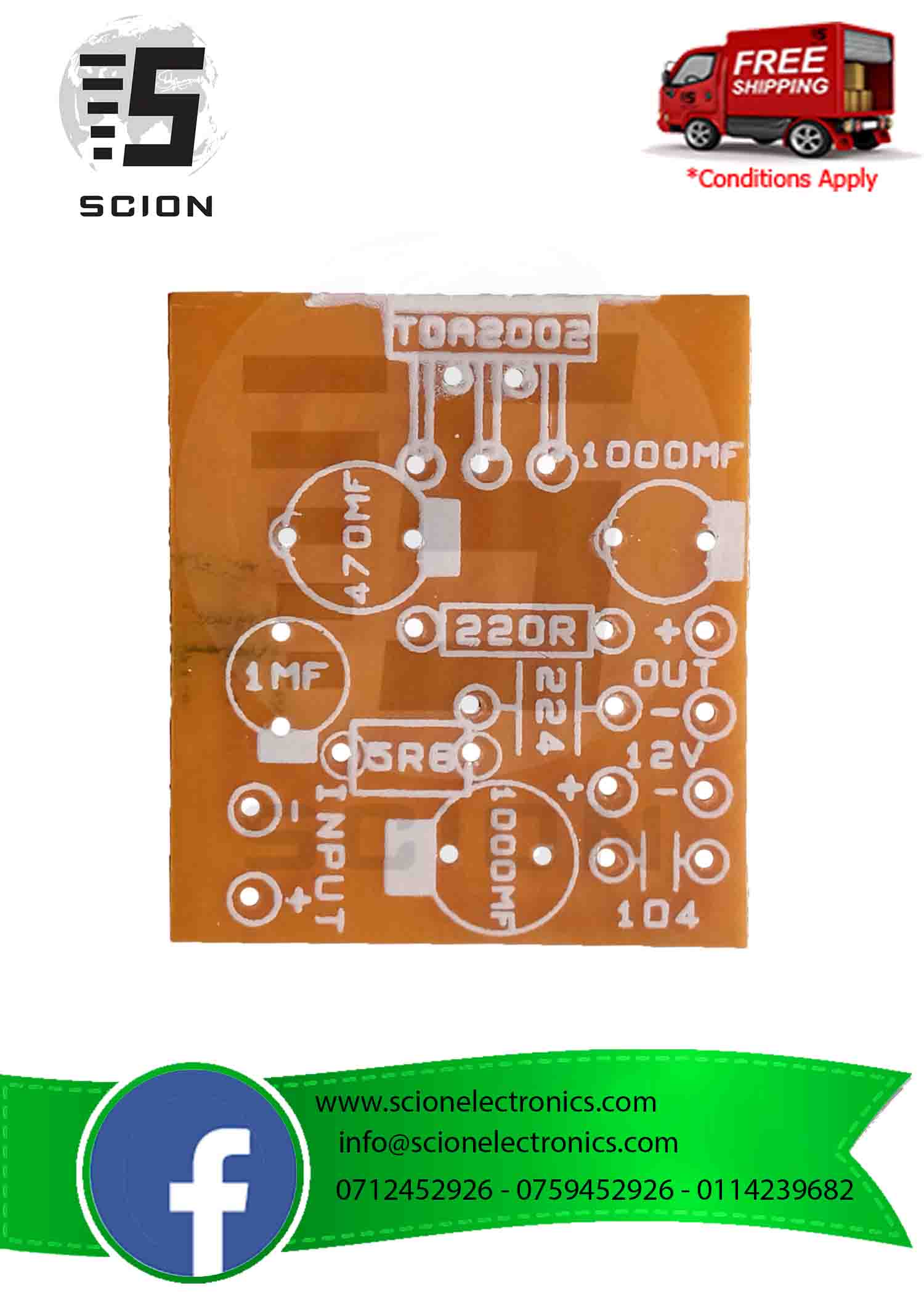
If Subwoofer in your music system is not producing enough bass then you can use this simple DIY circuit to enhance the Bass. In this project we are going to design a Subwoofer Amplifier Circuit Using IC TDA2030 with few cheap components.
- Tda2003 Pcb
- Tda2003 Pcb Holder
- Tda2003 Pin
- Skema Pcb Tda2003
- Tda2003 Pcb Board
- Tda2003 Pcb Rentals
- Tda2003 Pcb Wizard
Tda2003 Pcb
Find the PCB design here. TDA2003 is an integrated audio amplifier circuit capable of providing up to 10 W into 2 ohms load and 6 W into 4 ohms load when powered at 14.4 V. It is very easy to build a reliable circuit with it because it has short circuit protection. TDA2003 Ver1.0 9 Figure 20. Output power and drain Figure 21. Output power and drain current vs. Case temperature(RL=4Ω) current vs. Case temperature(RL=2Ω) PRATICAL CONSIDERATION Printed circuit board. TDA2003 2ch-Amplifier package IC Product information Manufacturer ST microelectronics ASIN B073YDFJRC Item model number pcb board Customer Reviews: 5.0 out of 5 stars.
If you would like to build a HI-FI power amplifier project that power output size about 30 watts to 50 watts or 75 watts at 8 ohms loudspeaker, and is high-quality sound and easy to build (not too many components).
We recommend you use TDA2050 class AB OCL amplifier circuits. Below that builds with the integrated circuit, PCB layout and no need for any customization. Parts used in this circuit are easily available in most of the local markets.
TDA2050 datasheet
The TDA2050 is class AB audio amplifier. Its high power capability the TDA2050 is able to provide up to 35W true rms power into speaker 4 ohm load at THD =10%, VS =±18V, f = 1KHz and up to 32W into 8ohm load @THD = 10%, VS = 22V, f = 1KHz.Moreover, the TDA 2050 delivers typically 50W
The pins connections
Tda2003 Pcb Holder
The schematic diagram
The music power into the 4-ohm load over 1 sec at VS=22.5V, f = 1KHz
May take an interest want to try build already, try out this circuit use voltage Vcc +/- 25V.
Here is TDA2050 I found on Amazon Read more
35 watts TDA2050 Amplifier mono
I know you want to see an example circuit. Here is a simple circuit.
Tda2003 Pin
Ready to get started?
Look:
Circuit diagram of 35 watts amplifier using TDA2050.
22V Dual Power Supply circuit for 35W amplifier.
Parts you will need
Electrolytic Capacitors
C1: 0.47 to 22uF 50V
C2: 22uF 35V
C6, C7: 2,200uF 50V
Mylar or Ceramic Capacitors
C3,C4: 0.1uF 50V
C5: 0.15uF or 0.1uF 63V
C8, C9: 0.1uF 63V
0.25W Resistors, 5% tolerance
R1, R3: 47K
R2: 1 to 3.3K or 680 ohms
R4: 1 to 4.7 ohms
PCB : 35W Hi-Fi AUDIO POWER AMPLIFIER by TDA2050
on PCB : 35W Hi-Fi AUDIO POWER AMPLIFIER by TDA2050
50W-75W Stereo power amplifier using TDA2050
We used the TDA2030 to build many power amplifier projects, but they have lower power than 30 watts.
Today, we try to use the TDA2050, which has the output power about 50 watts that shape and easy to use as well.

This project is stereo that easy to builds can adjust volume, tone and balanced sound.
First of all, we look at the circuit diagram below.
This circuit with a high current so takes low voltage 25V similar the normal 30 watts amplifier.
Skema Pcb Tda2003

Figure 1: the 35W + 35W stereo power amplifier circuit using TDA2050
We should use the 25V CT -25V high current power supply circuit with RFI filter system. Which have 4 x 2,200uF 50V are connected together in parallel.
Figure 2: the 25V CT -25V Dual power supply of this projects
We can boost up power output to 75 watts by the same voltage power supply.
In the circuit, we use both transistors 2N3055 NPN types and MJ2955 PNP type to increase current up.
Figure 3: the 50W + 50W (Max75W) stereo power amplifier project using TDA2050 and 2N3055-MJ2955
How to build
We do not need to explain a lot. Lets to build this project better.


Figure 4 the PCB layouts.
Figure 5 the component layout of this projects
Parts you will need
IC1, IC2: TDA2050
Cr: amazon.com by kunwangaetc
0.5W resistors, 5% Tolerance
R1, R8: 5.6K
R2, R9: 47K
R3, R18: 2.7K
R4, R11: 22K
R5, R12: 680 ohms
R6, R13: 22K
R7, R14: 1 ohms
R01, R02, R03, R04: 10 ohms 5W Resistors
Ceramic Capacitors
C1, C10: 47nF(0.047uF) 50V
C2, C4, C11, C13: 2.2nF(0.0022uF) 50V
C3, C7, C8, C9, C12, C16: 0.1uF 50V
Electrolytic Capacitors
C5, C14: 1uF 50V
C19, C20: 2,200uF 50V
C21: 2,200uF 80V
P1: 100KB, Dual Audio Potentiometer
P2: 100KA, Dual Audio Potentiometer
P3: 100K, Audio Potentiometer
Q1, Q3: MJ2955, PNP transistors
Q2, Q4: 2N3055, NPN transistors
Note:
On Figure 1 and Figure 3
R5,R12: 680 ohms, 0.5W Resistors 5%
R6,R13: 22K, 0.5W Resistors 5%
You can use TIP3055 instead of the 2N3055 and TIP2955 instead of MJ2955 because easy to use.
Tda2003 Pcb Board

Tda2003 Pcb Rentals
Related Posts
Tda2003 Pcb Wizard
GET UPDATE VIA EMAIL
I always try to make Electronics Learning Easy.